MATERIALS
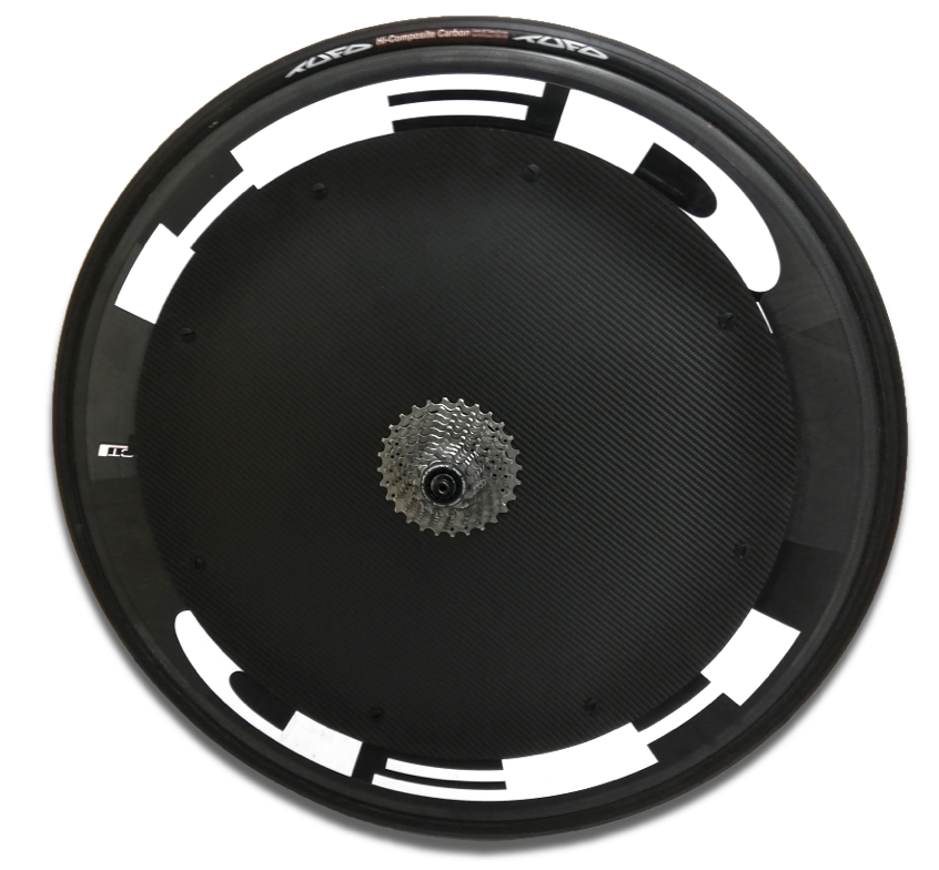
Laminar cover are two high strength (3k-HS) carbon fiber/epoxy composite made parts.
Each pair is manufactured to
Both covers are different due to the asymmetry of the road rear hubs.
In the drive side, the surface has less curvature and constant thickness.
On the other hand, the non-drive side, has more slope. The laminate has been optimized with a variable thickness; in order to stiff the necessary areas to avoid any bumps, but flexible enough to assure a proper fitting with the rim.
The valve hole to inflate the wheel is placed in the more adequate side (not the same for all the models) to avoid losses of stiffness and aerodynamic.
In addition, 10 more polyamide screws are provided (8+2) with a plain head but width enough to improve the fitting with the rim, with a minimum increase of weight.
Laminar Cover are provided with matt finish, naked carbon and without any decal.
AERODYNAMICS
Cyclist produced power is used to overcome the following types of resistances:
Apart from the last one, all the other components can be evaluated mathematically.
1. Power necessary to overcome aerodynamic resistance can be evaluated as:
being,
ρ: air density (kg/m3).
Vg: cyclist speed (m/s).
Va: air speed incising in the cyclist, or speed relative to the air (Vg+ Vair frontal )(m/s)
Cd: aerodynamic coefficient.
A: Area that the cyclist exposes to the air. (m2)
2. Rolling Resistance
Prolling = Crr x M x Vg; Ec.2
being,
Crr: Rolling Coefficient
M: mass (bicycle +cyclist) (kg)
Vg: cyclist speed(m/s)
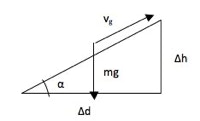
3. Power to overcome Gravity
Pg= M x g x Vg x sen (α); Ec. 3
sin α= sin (arctag(Δh/ Δd)); Ec. 4
Para ángulos pequeños, el seno se puede aproximar a la tangente, por lo que
sin α= Δh/ Δd =slope; Ec. 5
4. Power to accelerate
P = 0,5 x (M + I/r2)x (Vf2- Vi2)/(tf-ti); Ec. 6
being,
M: mass (bicycle +cyclist) (kg)
I: Wheels Inertia. (kgm2)
r: Wheel external radius (m)
Vf: final speed after acceleration (m/s).
Vf: initial speed before acceleration (m/s).
From all of them, quantitatively, aerodynamic resistance is the most important, but also the one that can be modified more easily.
For instance, if a cyclist rides with constant speed, in a plain road, without wind, and we consider the mechanical the friction as negligible:
with Crod de 0,0025, for a mass of 85kg, a speed 35 km/h, and a CdA of 0.41 the rolling resistance will be only 24,3w. That means, only a 9% of the total required power: 253w. As consequence, the 91% of the power is used to overcome the air resistance.
YAW ANGLE
Companies like HED or Zipp have published tunnel test data where they evaluate the benefits of an aerodynamic Wheel. These benefits are strongly dependent of the yaw angle.
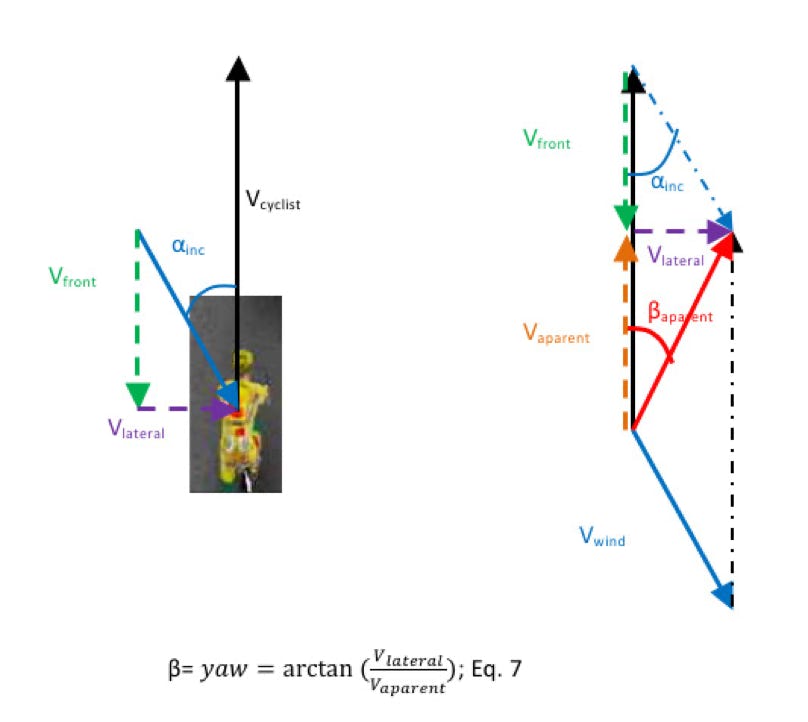
Yaw angle is the angle is not only the angle of incidence, but it depends also on:
-cyclist speed.
-wind speed.
-wind angle.
Vfrontal =Vwind x cos (α); Ec. 8
Vlateral =Vwind x sin (α); Ec. 9
Vaparent= Vwind - Vfrontal.; Ec. 10
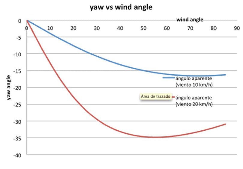
In order to show the values of the yaw angle in typical conditions, the next figures are shown:
For a typical constant speed of 35 km/h, and two wind speeds: (10 y 20 km/h), the following yaw angles are obtained for different wind angles of incidence.
It can be checked that for the specified conditions and a 10 km/h wind speed, yaw angle is always lower than 20°.
In the case of a 20 km/h wind speed, a yaw angle of 30°, can appear only if the angle of incidence is between 30° and 90°. In any case, a yaw of 35° is never reached.
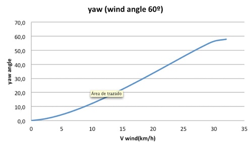
Moreover, in the following graphic it is shown how the yaw angle varies with the wind speed when wind angle of incidence is 60°, when the cyclist speed is again 35 km/h.
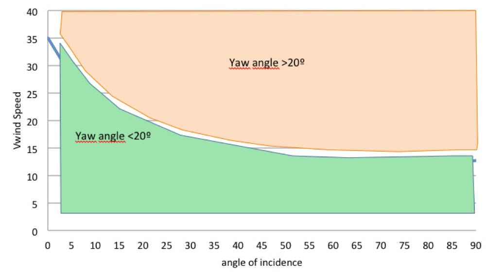
Finally, in the following graphic the conditions (wind speed and angle of incidence) where for a cyclist speed of 35 km/h the yaw angle are higher or lower than 20° are represented.
The wind tunnel data tests published are usually done only for yaw angles up to 20°. This does not mean that for higher yaw angles the performance of the wheels is necessary worse. Just there are not published data.
But what is demonstrated is the benefit of the aerodynamic wheels below 20°.
INPROVEMENT
Existen datos publicados por los fabricantes de ruedas más importantes del mundo, en los que se cuantifican estas ganancias. Sin embargo, al estar más expuesta al viento, una rueda delantera aporta más ventaja que la el mismo perfil en una rueda trasera.
Zipp presenta las mejoras de sus ruedas, cuantificadas en watios:
http://www.zipp.com/_media/pdfs/support/aero_edge09.pdf
Según sus datos, para un juego de ruedas de 58 mm de perfil (404) ahorra 23w. Los datos están referidos a un juego de ruedas base de Mavic Ksyrium. El ángulo aparente de viento es de 10 grados y la velocidad de 48km/h a 300 vatios.
Fuente:
http://www.amtriathlon.com/2008/04/impacto-aerodinmico-de-las-ruedas-zipp.html#ixzz0z7vvqxQs
Según Zipp, una lenticular trasera (Sub9) ahorraría otros 7w sobre el una trasera 404.
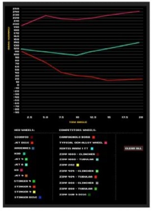
Más completa es la información que proporciona HED sobre sus ruedas, en las que aporta curvas del drag( (resistencia al aire en gf) en función del ángulo aparente, en un rango de 0º a 20º, que como se ha visto en el apartado El ángulo aparente, es un rango en el que se encuentran la mayoría de condiciones.
Si se compara un disco HED Jet, con una rueda HED Jet 6 (perfil de 60 mm), se puede ver cómo con un ángulo aparente de 0º la diferencia es prácticamente nula. Sin embargo, con un ángulo aparente de 15º, se obtiene la máxima diferencia entre ambos que es de 120- 10 = 110 gramos de drag. Frente a una rueda convencional, la diferencia es de unos 200 g. O lo que es lo mismo, 10 y 20 w para una velocidad de 35 km/h.
Esto quiere decir que con un ciclista a 35 km/h, con un viento de 15 km/h que incide sobre el ciclista con un ángulo de 60º, se obtiene el máximo beneficio: ¿cuánto?
Para un ciclista a 35 km/h, (que pueden suponerle tener que aplicar 245 w para superar la potencia aerodinámica, con una buena posición aerodinámica CdA=0.3), representa una ganancia de entre un 5 y un 10% en watios, que representan entre 0,6 y 1,2 km/h de aumento, que para una crono de 40 km suponen 70 y 140 segundos.
Para simplificar, dentro de este rango de velocidad y de estas potencias:
Por cada watio ahorrado, para 40 km, 6,5 seg de ahorro, por lo tanto:
En 40 km: 100 gramos drag -> 10 w -> 65 seg.

The Laminar Covers assemby is quite simple.
The pack includes:
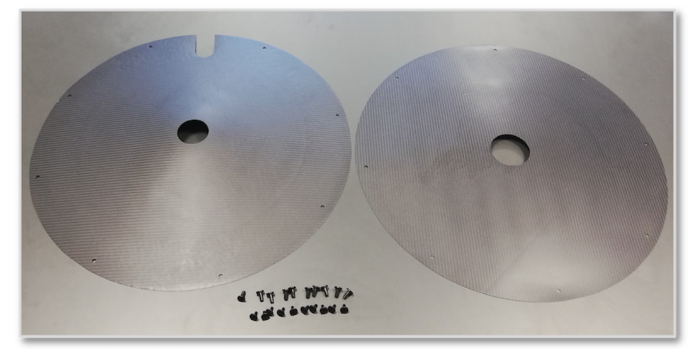
- One cover, plain, for the cassette side.
- One cover, lens-shaped for the opposite side (not necessarily of the same diameter than the plain one)
- 10 polyamide screws (male and female y hembra). 8 for the assembly and 2 spare screws.
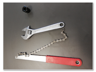
The necessary tools are (not included)
- a chain whip
- cassette cog remover tool
- wrench
The steps to install the laminar cover are the following:
1. ¿Can install Lamianr Covers in a front wheel?
Yes, but they are different from rear wheels covers, so you must indicate it in your order..
2. ¿Are my wheels compatible for Laminar cover installation?
Laminar Cover are specific for each model of wheel. They vary depending on the rim and the heb. We have a list of already demostrated as compatible wheels. If your wheel is not in the list, please contact us.
Compatible wheels:
Laminar covers are not compatible with following bikes:
- Trek Speed Concept
- Blue Triad
Laminar covers are not compatible with following wheels:
- Campagnolo Bullet
- PlanetX 82
- Easton EC 90 Aero 90
If you have any doubt or need more information, don't hesitate to contact us: EMAIL
For national shipping, it will be done by NACEX. The cost is 25 euros.
For international shipping, please ask for quotation.
In accordance with the provisions of Law 15/1999 of December 13, Protection of Personal Data, IDEC, SL informs you that the data provided through this form will be included in a file owned by IDEC , SL, being used to provide the information that you request or manage the services you require.
The sending of such data implies their consent to proceed with the processing of them, including their email address, for the purposes identified in the previous paragraph.
You may exercise your rights of access, rectification, cancellation and opposition with proof of identity, addressing IDEC, SL Albert Einstein, 29, 01510, Minor Miñano (Alava) or the email address
IDEC, Ingeniería y Desarrollos en composites, S.L activities are focused on the new materials engineering, especially in advanced composites. IDEC develops its applications in composites taking the advantages that the new materials offer for different sectors (aerospatial, industries).
Where we are
IDEC, Ingeniería y Desarrollos en composites, S.L, is sited in the Alava Technology Park. Founded in 1992, the Technology Park of Álava is a bet of the of the Basque Public Administration (Basque Government, provincial Council of Álava and Town Council of Vitoria-Gasteiz) with the aim to diversify the Basque business network towards the company of the future, promoting the following features in the same environment:
The unbeatable geographic location –at the best communication node with the roads N-1, N-240, the Vitoria/Eibar highway, the highway to Bilbao and the Airport– makes the Alava Technology Park a strategic place for corporate implementation and development.
Copyright © 2020
Aceptar